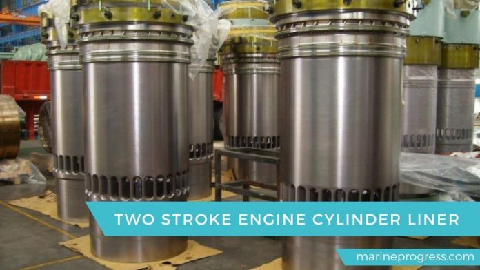
The cylinder liner forms the cylindrical space in which the piston reciprocates.
The lip on the upper part of the cylinder liner sits on a machined face. It is on the top of the cylinder block. And the liner held in place by the cylinder cover. This arrangement allows the linear to expand freely downward when it heats during the running of the engine. A cooling water space between the cylinder block and the liner sealed at its lowest part. This could do by silicone rubber “O’ ring. The sealing arrangement actually consists of two things which fit in machined grooves in the liner. The upper one acts as a seal for the water jacket. At the same time, the lower one prevents air leaking from the scavenge space.

A tell-tale hole is provided in the cylinder block between the two ‘O rings. Any leakage from this indicates the failure of the water or air ‘O’ Tings. Scavenge airports cut in the lower section of the liner. The exhaust ports also cut if the engine operates With loop scavenging. And these ports machined at an oblique angle to the axis of the cylinder. This makes sure the impart a rotary motion to the incoming scavenge air.
Liners may manufacture from grey cast iron. But the cylinder liners for modem highly rated engines manufacture from a sophisticated cast iron alloy. This provides a high degree of ductility to resist thermal stress and at the same time provide good wear resistance. The upper part of the liner close to the combustion zone is the critical region. This is due to high pressure and high thermal loadings. There are conflicts on how these requirements can meet. A thick wall section requires to resist the high pressure. Thus, to provide effective cooling, which avoids high temperature, it is necessary to have the cooling medium as close as possible to the heat source.
In these circumstances ‘bore cooling’ use as thick sections and a cooling arrangement Close to the heat source. The liner surface, sometimes finished using wave grinding. The surface looks to have a very fine finish but on a microscopic scale. it is undulating to allow for rapid running-in and to provide a key for lubricating oil which carries away the metal particles from the running-in wear process.
Liner calibration takes at every unit overhaul to know the wear down of liner. For slow speed engine, maximum wear down is 0.8 to 1% of the original bore diameter.
First clean liner thoroughly. Liner calibration takes using inside micrometre with extension bar which has been calibrated against a master gauge. The diameter measures both in the fore and aft and athwartships direction. The micrometre should be at the same temperature as the liner.
The measurements can directly compare to previous Readings and a wear rate calculated. It allows for the wear rate of the liner to calculate in mm/1000 hrs. This wear rate varies. But approximate figures are about 0.05mm/1000hrs for a two-stroke crosshead engine and about 0.01 5mm for a four-stroke trunk piston engine.
If this is in excess of the manufacturer’s recommendations, then the piston rings will not seal effectively, leading to blow-by, even more, wear, loss of power and scavenge fires. Ovality can also determine. This can become a problem on trunk piston engines, in which the piston skirt transmits side thrust to the liner.
A Cylinder cover and cooling-water jacket
The cylinder cover manufactures in steel. And it has a central bore for the exhaust valve, which is attached by means of four studs. The cover furthermore has bores for the fuel valves. These are mounted with tubular spacers and nuts.
Other bores have been provided for starting valve, starting air inlet, safety valve and indicator cock.

A cooling jacket mounts on the lower part of the cylinder cover, whereby a cooling water space is formed.
Another cooling water space creates around the exhaust valve seat when the exhaust valve is installed. These two spaces communicate through a large number of oblique/radial cooling bores in the cover.
The water supplies from the cooling jacket surrounding the cylinder liner and passes through water transitions to the cooling jacket surrounding the cylinder cover. Further on, through the cooling bores, to the space around the exhaust valve seat. Then the water discharge to the main cooling water outlet pipe.
The cylinder cover tightened against the top of the cylinder liner by means of nuts and long studs fitted in the cylinder frame. The nuts should tighten by hydraulic jacks.
The sealing between the cylinder cover and cylinder liner obtain by means of a sealing ring, made of mild steel.

