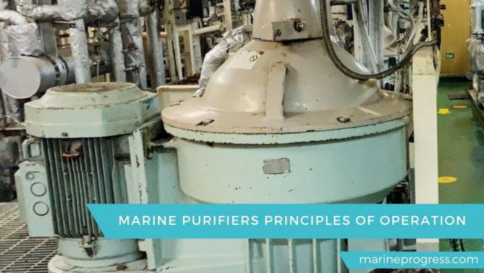
purifier and system principles
The basic operating principle of the purifier
An efficient combustion in marine engines requires good quality fuel oil. The heavy oil used in engines is not of the purest form. In order to clean this dirty fuel, oil is sent through a series of purifying equipment’s before it reaches the engine. Separators / purifiers, clarifiers are two such equipment’s that are used for purifying and filtering the fuel oil to separate solid particles and / or water.
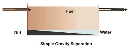
The easiest of ways of cleaning of fuel is through the method of gravity separation. Gravity is made use of in this method which separates fuel from impurities and water that are heavier than the fuel which floats at the top and is collected through an outlet that is made at the top of the container. The impurities and water can be finally removed by draining of the tank at last.
Centrifuging is the process that is used for faster and most efficient cleaning of fuel. There are separators that work on the principle of centrifuging.
However, they are divided on the basis of what they separate from the fuel. Separators that remove water / solids from the fuel are called purifiers whereas those that remove solid impurities are called clarifiers.
Centrifugal force:
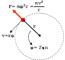

Centrifuging is a process that amplifies the effect of gravity and makes the process of purification faster and more efficient.
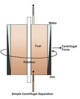
Centrifuges work by rapidly spinning a bowl containing the liquid, thus producing the required centrifugal force to produce separation.
The principle of operation of the centrifuge is simple. When a bowl containing impure fuel is rotated, centrifugal forces will throw any item with density greater than the fuel oil density (solids and water) to the periphery of the bowl while fuel that has the lowest density remains at the center.
Centrifugal separators used for the separation of two liquids of different densities (fuel and water) are known as purifiers and those used for separating solid impurities are known as clarifiers. Purifiers will also remove some solids and clarifiers will also remove small quantities of water.
Basic construction of the purifier
Purifier
When a centrifuge is set up as a purifier, a second outlet pipe is used for discharging water as shown.

In the fuel oil purifier, the untreated fuel contains a mixture of oil, solids and water, which the centrifuge separates into three layers. While in operation, a quantity of oil remains in the bowl to form a complete seal around the underside of the top disc and, because of the density difference, confines the oil within the outside diameter of the top disc. It is necessary to prime the bowl each time that it is run; otherwise all the oil will pass over the water outlet side to waste. The water outlet is at greater radius than that of the fuel. Within the water outlet there is a gravity disc (shown in green), which controls the radial position of the fuel water interface.
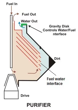

A set of gravity discs is supplied with each machine and the optimum size to be fitted depends on the density of the untreated oil. When the fuel centrifuge is operating, particulate matter will accumulate on the walls of the bowl. If the centrifuge is set as a clarifier, the particulate matter will be a combination of water and solid material. If it is set as a purifier, the free water is continuously discharged. Therefore, the particulate matter will consist of solid material. In older machines it is necessary to stop the centrifuge to manually clean the bowl and disc stack, however, the majority of machines today can discharge the bowl contents while the centrifuge is running.
Construction

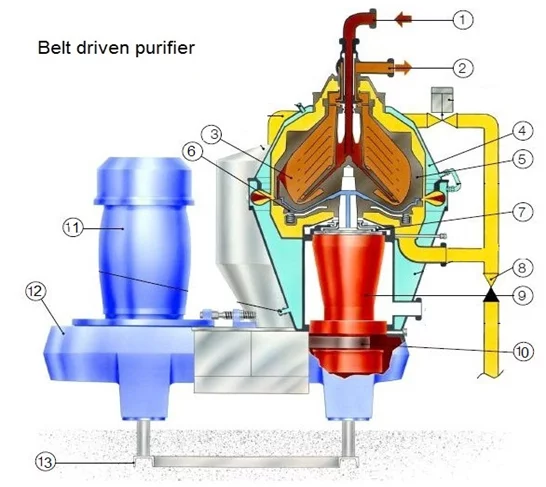
1. Feed valve 2. Clean oil out 3. Liquid 4. Housing 5. Bowl
6. Spring 7. Operating water distributor 8. Check valve 9. Bearing housing
10. Drive belt 11. Electric motor 12. Gearbox 13. Foundation
Basic components of the centrifuge are as follows:
Exterior framework:
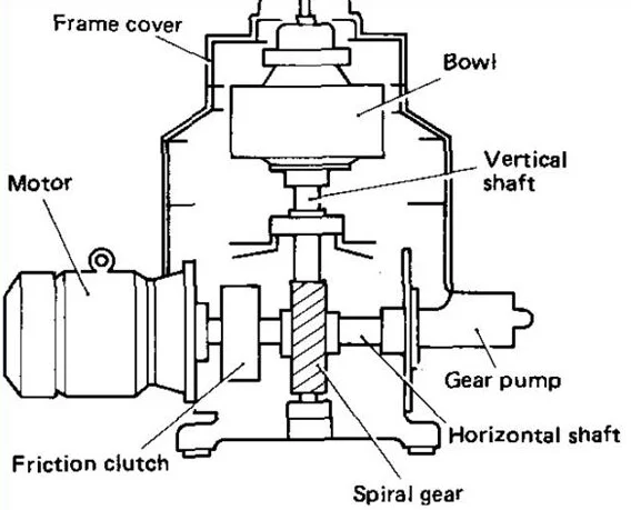
The exterior frame work is normally made up of caste iron which supports the internal bowl and disk parts and carries water line, feed line and outlet line connections.
Bowl and disk:

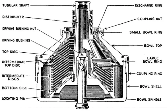
There are bowls inside the frame, which can be a solid assembly operating continuously and have space enough to retain the separated sludge. There can also be an arrangement in which the upper and lower parts are separate for discharging the accumulated sludge during operation. These parts are normally made up of high tension stainless steel.
Disks improve the purifying efficiency.


Vertical shaft:
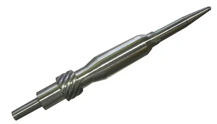
The Vertical shaft is used to transform the electrical motor output into rotational motion for rotating the bowl in high speed through spur gear and horizontal shaft or belt. The material used for vertical shaft construction is an alloy of steel.
Horizontal shaft or belt drive:
The electrical motor drives the horizontal shaft through clutch pads and is used for transmitting the rotational motion to bowl assembly. A special belt having elastic character is used in some models in place of horizontal shaft, thus removing the use of the gear assembly. The horizontal shaft material is a special alloy of steel.
Spiral gear:
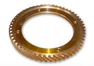
A spiral gear is placed between the horizontal and vertical shafts for the transfer of rotational motion. These gears are manufactured by special aluminum bronze material.
Clutch or friction pads:
An electric motor will get overloaded if it is connected directly to the bowl assembly for the rotation of the same as the complete assembly is very heavier. To avoid this, clutch or friction pads and drum assembly are installed on the horizontal shaft. Normally the number of pads varies from 2 to 4 depending upon the frequency supply to the motor.


As the motor starts, the pads inside the drum moves out gradually due to centrifugal force and cause friction in the internal wall of the drum resulting in rotation of the shaft and the bowl gradually without overloading and damaging the motor and gears.
Attached Gear pump:
A general construction of centrifuge consists of a horizontal shaft driven attached supply or discharge gear pump. In some system an external supply pump may be installed in place of the attached pump
Sludge discharge mechanism
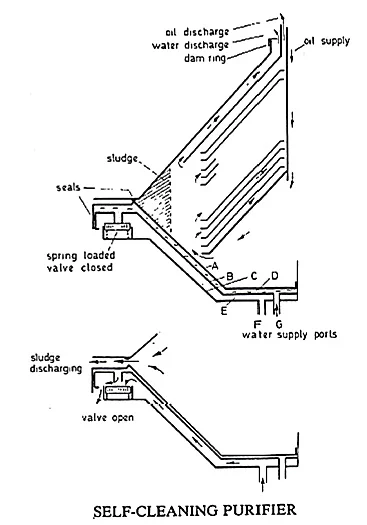
Fig. shows diagrammatically the method of sealing and sludge ejection for a self-cleaning purifier.
Bowl sections A, B and C, are all keyed to the central drive spindle, B and C, and are secured so that they cannot move vertically whereas A is free.
The purifier is first brought up to operating speed and water is then supplied to space D through supply port G. Due to centrifugal force the water pressure in space D moves A vertically to form a seal at the bowl periphery. Water and then oil would next be supplied to the purifier in the usual way.
When the purifier requires to be cleared of sludge the oil supply is shut off and water supply is changed over from G to F supply port. The hydraulic pressure created in space E is sufficient to open the spring-loaded valves and the water from space D will-together with water from space E-be discharged and A will fall, the bowl seal will now be broken and the sludge ejection will take place. After de slugging is completed the water supply will change from F to G. The spring load v/v will close & start pressuring the space D to shut the bowl for the next cycle.
Sequence of discharge sludge
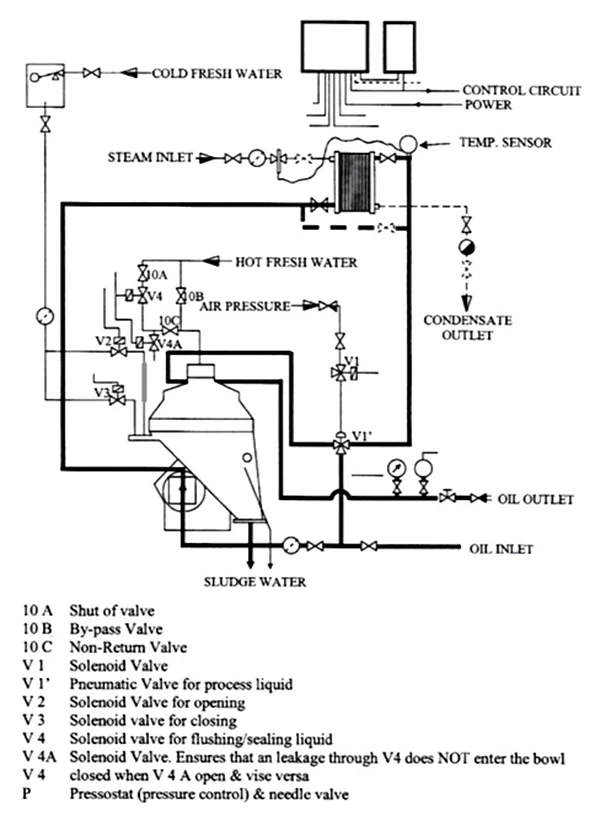
When sludge discharge cycle initiates
- V1 valve operates and oil inlet by pass the purifier
- V4 opens for few second and supplies water to the bowl
- V3 closes, Bowl closing water stops
- V2 opens, Bowl opening water open
- Purifier desludge
- Why purifier needs following data concerning temperature, quantity of flow and density
Temperature
HFO viscosity decrease with increasing temperature, so the separation process accelerates as the resistance to flow (viscosity) is decreased. It means due to less resistance to flow, water and solid particles easily separates.
Density
In a purifier separation takes place due to density differences. Internal diameter of the gravity disk depends on fuel density and selection of correct gravity disk is very important. If the wrong dam ring (gravity disk) is selected water may carry out with clean oil or oil can be seen at the water out let.
Flow rate

Purifier flow rate should be correctly matched with engine consumption and it should be at the optimum throughput rate as possible but to be just above total fuel consumption.
Difference between purifying and clarifying
When two liquids of different densities are separated using a centrifuge, the equipment is labeled as a purifier, but when the same centrifuge is used to separate solid impurities from the fuel, it is called a clarifier.
A clarifier works as a backup system if one feels that purifier has not completely removed dissolved solid impurities from the fuel.
Purifiers have a Gravity disc / dam ring that works to create a line of separation between fuel and water. However, in clarifiers, instead of a gravity disc, a sealing ring is used that prevents water and dissolved impurities to remain inside the purifier bowl.

Purifier
• The discs have holes
• Separates water & heavy solid impurities
• Two outlets on top, each for water & oil
• Gravity disc on top of disc stack.
• Require sealing water while starting.
Clarifier
• The discs have no holes.
• Separates only solid particles.
• There is only one outlet on top.
• No gravity disk ( a disk is used to completely seal the water outlet)
• Sealing water is not required.

